
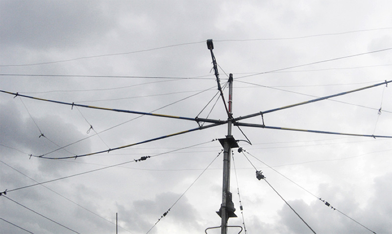
Why did I choose Moxon? I have always been fascinated by cubical quad antennas and I wanted to make one when I got my 1st radio, I guess it’s innate among members of our school radio club . I even purchased all the materials for a dual band cubical quad, only to realize during assembly that my roof space is not enough for a bulky and heavy antenna. Since then I have to make use of different kinds of small beam antennas until I came across Moxon antennas in 2005. It was the next best option to having a quad . I made an experimental mono band moxon for 15 mtrs using some of the materials I intended to use for my planned quad .The same wire elements, blue pvc spreaders , aluminum angular bar spreader support, U-bolts and hose clamps, it did not cost me anything making this antenna, and I had to make one element instead of the 2 elements for a quad. I only need to reconfigure the spreader support and make it intersect with two 40 degree angles on opposite sides.
Building a moxon is easy since you can work on it on a horizontal plane, then tune it by adjusting the length of the driven element , the distance between the 2 elements should be maintained. Although the resonant freq for this one is a bit below the 15 mtr Amateur Band , it performed well giving me solid dx qso's . After 2 broken spreaders due to different strong typhoons , it was time to replace this mono bander, it has served it’s purpose for 7 years or so.
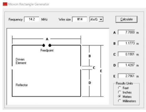
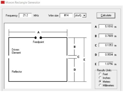
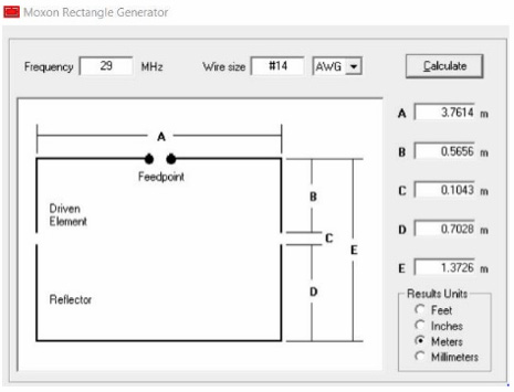
First, determine the dimensions for the wire elements using the MOXGEN Calculator, this software is available online for download. http://moxgen.software.informer.com/1.0/
Length of wire -
| 14 mhz approx. 20.612 mtr
Dr el = 10.055 mtr Ref el= 10.558 mtr |
21 mhz approx. 13.781 mtr
Dr el = 6.713 mtr Ref el= 7.070 mtr |
28 mhz approx 10.237 mtr
Dr el = 4.979 mtr Ref el= 5.258 mtr |
The total length of #14 awg used for the elements is 44.63 mtrs. I used an enamel copper wire for the elements. There are no restrictions regarding the use of materials, it really depends on what you have available and what you need based on your design. While building this project , I have been exchanging notes with my friend Markus Springfield - DL2GMS, I requested him do simulations on insulated wires, here's what we found out .
| wire dia. [mm2] | insulation material | insulation thickness [mm] | lowest SWR @ [Mhz] |
|---|---|---|---|
| 2.14 | none | none | 14.2 |
| 2.14 | PVC | 0.7 | 13.7 |
| 2.14 | PTFE | 0.5 | 14 |
I experienced the same results on my 1st Moxon for 15 meter band, I used an insulated wire and the resonant freq. was a bit below 21 mhz.
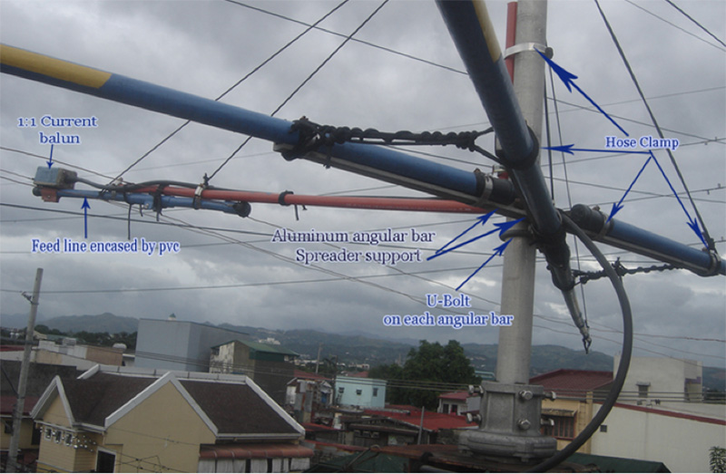
4 pcs spreaders - Since the turning radius is approx 4.18 mtrs or 13.54 ft. you may use 2 rigid pvc and make it telescopic for each spreader. The orange type appears more firm and sturdier than the blue ones. For my spreaders I used 4 - 16 ft fishing poles, and thanks to PJ and Alex for their help in finding them. An important consideration is to treat your spreader with weather proof coating. I addressed this problem on my fishing pole by reinforcing the joints with fiberglass and by applying “ GEL-KOTE” (product label of premixed coating material for fiberglass) on the whole length of the pole.
Spreader Support - I used 2 pcs of aluminum angular bars 3 ft long, the same spreader support I used on my 1st mono band moxon. You can design your own spreader support with materials available to you. But I will advice that you use aluminum plates instead of the angular bar for easier assembly. Using aluminum is better since it is lighter than steel plates.
Hose clamp and U-Bolt (preferably stainless steel)
8 pcs for spreaders
2 pcs for the feed line support
2 pcs (based on the size of the center post) which is clamped to the center post. This can be omitted if you use plates instead of angular bars.
2 pcs U bolt for the spreader support for to be clamped to the center post too.( For angular bar)
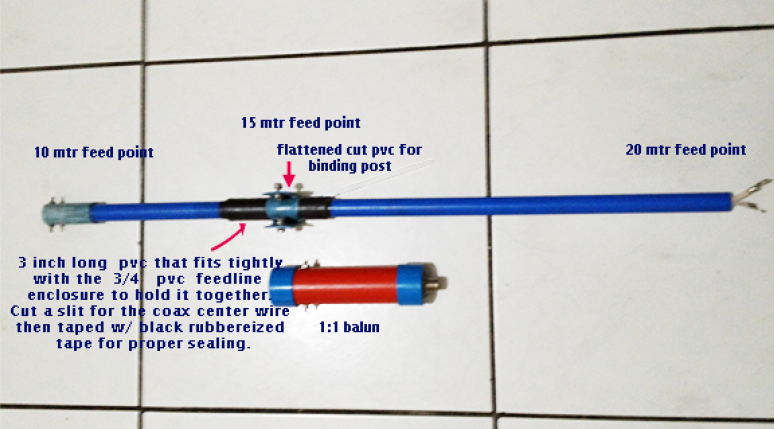
Feed line 4 mtrs RG58 (follow the design ) I inserted the feed line into a 3/4 in. pvc as casing
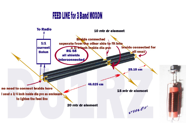
Balun (voltage balun), preferably a 1:1 current balun. If you plan on making one, as I did you may use the same #14 copper wire for the windings (around 4 mtrs.).
Feed Line Assembly and Balun (actual picture)
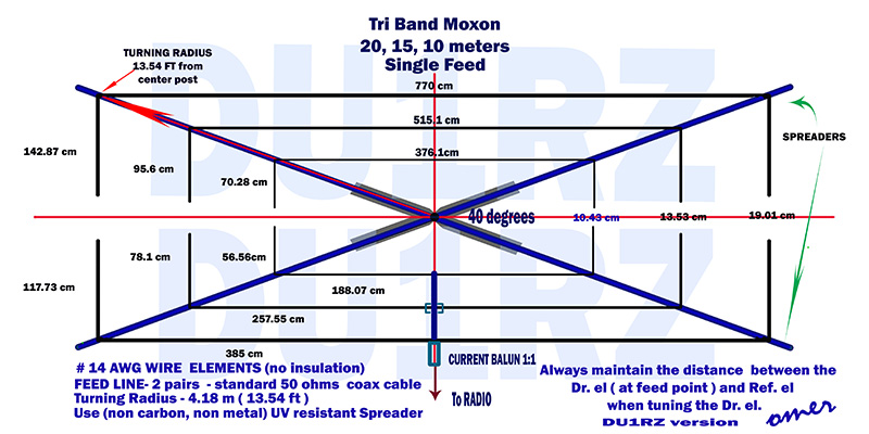
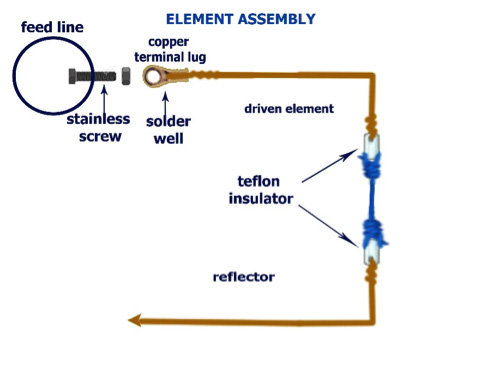
Prepare the wire elements according to the lengths from the Moxgen data results , or you may follow my design. Add some length on the elements for tuning and tail braid on the insulators. Assemble the spreader and lay out the elements, you’re now ready to connect the feed points of the 3 driven element to the feed line. For insulations between dr. and ref. element, I used scrap teflon.
I raised my antenna to around 10 ft for tuning purposes, and measured the swr to be around 2:1 on each of the 3 bands.
However , when I raised it on my mast the SWRs measured were:
FOR 14.225 MHZ is 1.0:1
FOR 21.250 MHZ is 1.1:1
FOR 28.50 MHZ is 1.3:1
The SWR measured on the WARC bands are reasonable too. I am not capable of doing simulations on this antenna , but me and 4F1BYN did some transmission test and found that the signal strengths between front and back signals is around 2 S units with an out put power of 10 watts, and negligible signals on the side lobes.
If you plan on making one, I suggest that you proceed with materials that are easily available , you don’t need to copy exactly what I did, since I adapted my design on what I already have.
The materials I purchased were: 1 kg of copper wire , 4 fishing poles , 4 mtrs of belden RG58, and some hose clamps.
Some observations I share with Markus ( DL2GMS ):
- Performs great on 20, 15, 10
- nice front/back ratio for a 2-element
- full bandwidth for 20, 15 with SWR < 1.2,
- however, on 28.2MHz … 28.7MHz below SWR 1.5
- small size: turning radius of abt. 4.18 (13.54 ft) suitable for restricted antenna space
- extremely low wind load for a “kW“-Antenna
- it is so light weight and easy to a raise into a mast.
Please look up for Markus’ (DL2GMS) design for another version of the same antenna.
Have fun with the project and enjoy your Dxing!
Email address: projmark@yahoo.com
@ QRZ.COM
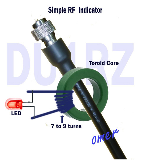
Here’s a simple RF indicator you can build to monitor rfi issues on your system.
The LED lights whenever you have RF on your antenna system.
"Just built the moxon you described. Absolutely matched easily and performs as you described. Great resource.
Thanks for publishing.
73 Drew VE3UIN"
"Hi Omer,
For reference, I'm at FN14rf.
The farthest I have done so far is VO1RCH on the east of Newfoundland. I'm regularly into Missouri, Alabama, Florida and Texas. I have heard French Guyana, France, and a sailing vessel at the mouth of the Amazon.
20m has been spotty since I built it, so I'm just testing it out for the past two weeks.
I'll post a short video of the same signal from the moxon, a 20m dipole beside it, and a B&W 1.8-30 at 20 feet apex.
I've noticed that the signals are usually 2-3 S units above the dipole and the B&W.
I sometimes get better signal reports on transmit than I experience on receive, and sometimes I have to switch between the moxon and the B&W so they can hear me, and then I can gear them. The latter is for marginal conditions.
The fishing poles I bought are much less expensive in the US, so the real cost would be a bit less elsewhere.
73 de VE3UIN
Drew"